CNC Software Education
Although VCarve doesn’t have 3D modeling capabilies, it can import 3D models created in other software or found online. Importing the Model Create a file as you typically would. Then click File > Import > Import Component / 3D Model and open a 3D file. VCarve accepts multiple 3D model file types. The most common is format is probably a stereolithography file (.STL).
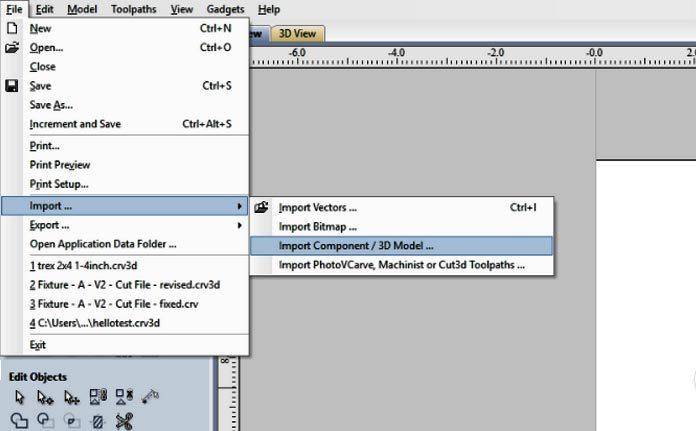
VCarve will switch to a 3D preview of the model with orientation options to the left. You may need to change the orientation of the model in the Initial Orientation panel, adjust the dimensions in the Model Size panel, and Alter the Zero Plane Position (often “Bottom” is preferable). When you click Okay the model will be confirmed and added to your Component Tree (viewable in the Modeling Tab).
Note: The top of your model must be below the top of your stock. Your stock size and model height can be adjusted after confirming, but it’s always better to think about this ahead of time.
Toolpathing
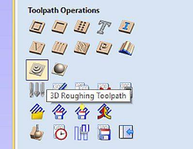
Toolpathing operations include two steps. First is the roughing operation which clears away excess material. This is followed by a finishing operation that contours the model. The roughing and finishing operations are the last two options in the Toolpath Operations panel.
As far as tool selection goes, a large flat-end tool is ideal for roughing and ball-end tools are typically used for finishing (the diameter of the finishing bit is determined by the level of detail required). Stepover is a critical factor for speed and finish quality. Roughing operations can have a large step-over, but finishing operations will need to be 5% to 20% of the bit diameter for the best results. Lowering the step over percentage will drastically lengthen the machining time so optimizing this value for the required quality is important if machining time per unit is important for your project. Stepover can be adjusted by editing the tool. Note: If your part is relatively shallow you may be able to avoid the roughing operation altogether. In order to avoid breaking the bit, it’s often best to choose parallel finishing at a 45 degree angle.
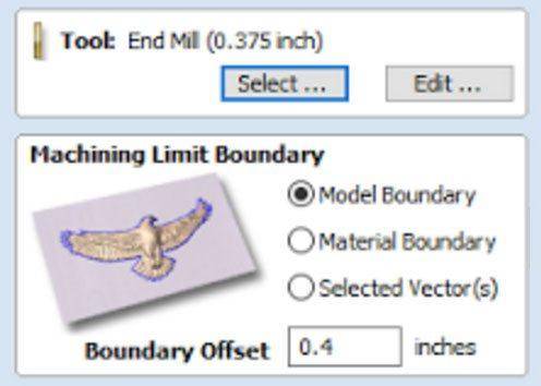
The selected vector can be very handy if you only need to perform 3D operations on a portion of the 3D model rather than the entire model. Once you’ve calculated the roughing operation and finish operation you can post these out using the same post processor you use for 2.5D operations.
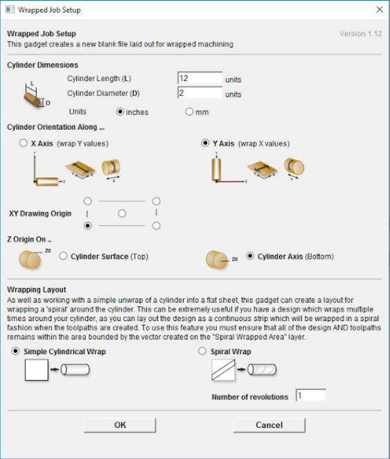
To wrap a project around the rotary axis following these steps
- Do not begin a new document
- Select Gadgets > Wrapping > Wrapped Job Setup
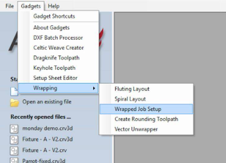
- Set your cylinder length and diameter
- Choose to wrap around the Y axis
- Click OK
- Proceed to draw the file as you normally would in a typical document. It will wrap the X direction as your rotational axis
- You can preview the wrapped job in the 3D Preview tab by selecting Toolpaths > Toolpath Drawing > Wrap X Values
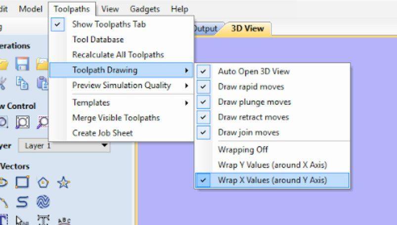
- You can preview the wrapped job in the 3D Preview tab by selecting Toolpaths > Toolpath Drawing > Wrap X Values
- When you are happy with the result, post out the file using the correct post processor. The correct Post Processor for the Laguna IQ is the Laguna_HHC_Rotary_YAxis post processor
- If you used the same job setup as I used in this example, your IQ Origin will be:
- X: centered along the rotational axis
- Y: lowest point on the turned part (I usually leave a .5” margin to avoid hitting the chuck)
- Z: centered along the rotational axis
This is quick walkthrough on how to not cut through your spoil board When first getting set up on your machine you may find that even after touching off your tool you are cutting above your material or through your spoil board. This is often caused by choosing the inappropriate setting in your CAM program.
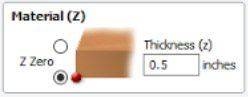
In nearly every CAM program you will decide where to set your origin, and specific to the Z, you will need to decide whether you are referencing the top or bottom of your stock material. Which is the better choice? Generally speaking, if you have a fixed tool touch-off point with a vacuum table and/or if you are cutting through the material, you want to reference the bottom of your material (top of the spoil board). If you are doing detailed engravings you may want to reference the top of your material. What does this mean when I run a file on my machine? When you attempt to run the file on your CNC machine you need to remember whether you’ve used top or bottom, and when setting your Z Zero on the machine you should match those settings. If you choose to reference the bottom of the material in your CAM software you should set your Z Zero to the bottom of the stock material on your machine (top of the spoil board). Conversely, if you choose the top of the material as your reference point you should touch your tool off to the top of the material. This will require either a movable touch-off puck or manually touching off the tool.

